Garrattfan's Modelrailroading Pages
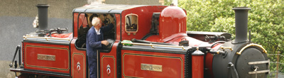
Fairlie Merddin Emrys
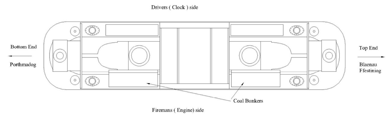
5.8 Detailing the power bogies
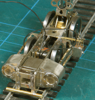
| Detailing the power bogie is not nearly as much work as detailing a locomotive body, yet it may take considerable time. I set out detailing in the first weekend of December 2016 and expected to have things done in the following two weekends, so before the start of my Christmas leave (16-12-2016). But in fact when that leave started I was still dogging on and it took me the better part of my first holiday week to get it all finished. But then again, I am not a fast builder. I take my time, prefer to work slowly and carefully, and simply enjoy the process rather than the speedy result. I also can't work eight or more hours in one go. I switch between building and reading and updating my website. But at last on 22 December 2016 I finished both power bogies. Here is the story of the detailing process, which has a lot more detail than the manual. | |
LubricatorsI accidentally started with the lubricators, because I somehow had swapped the pages in my printed manual ;-) Not much of a problem though, although you constantly have to be wary not to damage the lubricators when you are doing the rest of the work. So it is a logical thing to do the lubricators last. |
|
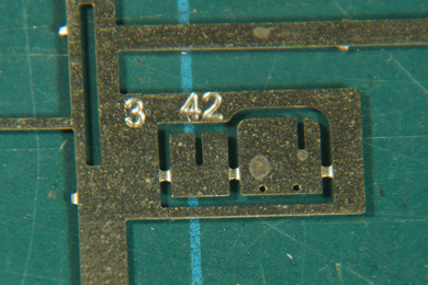 |
[200] Fit the lubricator bracket to the motion bracket. It took me some time to identify the bracket for the lubricator. I should have looked in the power bogie's parts list, that would have been very useful. Now I found the bracket via one of the very helpful photos that are included on the DVD that is included in the kit. To make it simple for you: it is number 42 and looks like the left photo on the etch. |
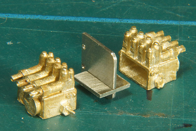 |
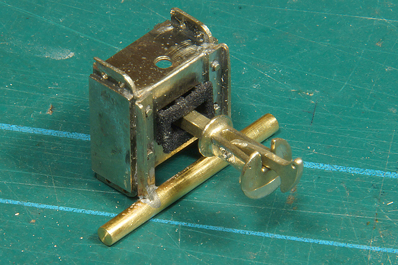
This is how the bracket goes together after removal from the fret and some filing and sanding. You have to decide whether you need one or two lubricators per bogie. Common practise on the FR is now to fit two lubricators to each bogie, but Merddin Emrys still had one on each bogie at the time I saw her (2011).
Not that the lubricators are lying on their back. Little error of the photographer, oopsy.
|
 |
A little help to solder the two tiny parts square is needed. I used 240C solder here, because the lubricator also needs to be soldered on. For now I did not worry about the two-sided bracket, for two lubricators, as this makes soldering so much easier. |
 |
The bracket is mounted with the pin and solder method with 180C solder. Be careful as the motion bracket is flimsy and will bend easily. |
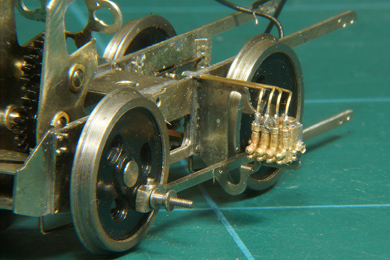 |
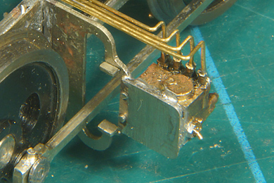
First the four oil feeds are soldered in their respective holes of the lubricator. Here I used 240C solder.
Then I soldered the lubricator to the bracket with 145C solder. After that I bent the feeds as desired and soldered them to the top of the frame. |
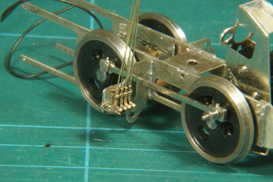 |
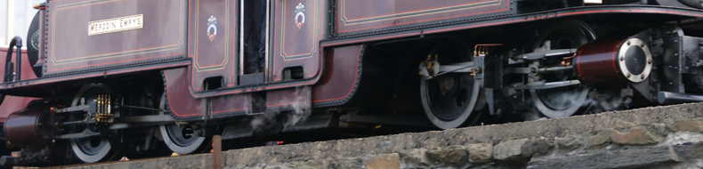
This is the lubricator on the other bogie in the process of feeder bending. Appreciate that both lubricators are on the same side and by installing them you make the bogies handed. Both lubricators are on the driver's side that is left when running towards Blaenau. Consequently this is the Blaenau facing bogie and the one on the previous photo will be the Porthmadog facing bogie. Also note that both lubricators face inwards, towards the firebox. |
Drawing used with kind permission of Paul Martin ©2013 EDM Models |
|
A shot from Merddin passing Boston Lodge towards Porthmadog (right) says it all. |
|
 |
To finish work on the lubricator the front end of the horizontal part of the lubricator bracket is snipped off and filed flush. |
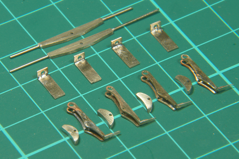
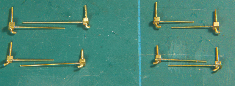
Crash bars |
|
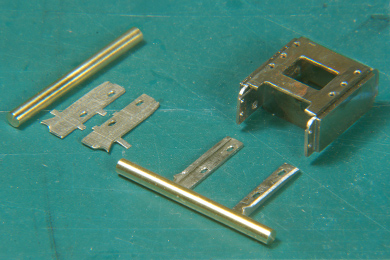 |
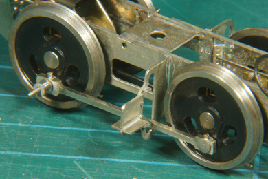
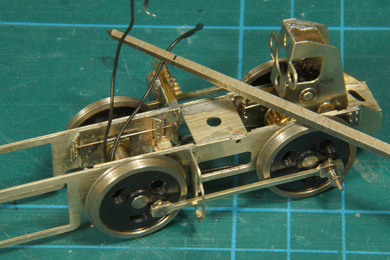
Now comes a good exercise in fiddly, patience wrecking work adding the crash bars.
Cut the crash bars from ttwo pieces of brass rod, 2 mm diameter at a length of 22mm. Retrieve the brackets from your storage box. They won't be on the fret anymore as they came away when you freed up the front buffer beam etch (see instruction [23]). |
The original location of the crash beam brackets. |
|
 |
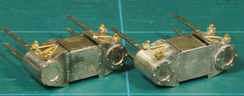
Getting the brackets on the front buffer beam and stay put proved to be a pain. After a time of experimenting with the least uncomfortable way of scorching my fingers I clamped the whole bogie between two large paint stirring sticks and put it in my vise. This and aided by the pins to locate the bracket gave me the direly needed extra hand to keep everything in place while soldering. I used 180C solder and went in and out quickly before the buffer beam came apart. The brackets have longitudinal holes so you can move them vertically. This is aimed to getting the crash bar absolutely horizontal. This is essential as the "face" of the locomotive is unproportionally impeded if the crash bar is not level. Again a lot of fiddling taught me that you can't position and solder two brackets at the same time (!). The fiddling also showed me that getting it dead level wasn't going to stress the play in both brackets. So I soldered one bracket in the mid position and set out to determine the position of the other bracket. |
 |
That was done by taking the bogie out of the vise, turn it upside down and lay the crash bar on both brackets and try to establish the best position for the one bracket that had not yet been fixed. Check, check and check over and over again.
|
 |
|
 |
Then, when satisfied, tack solder the second bracket and check again. If necessary take it apart and try again.
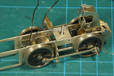
Finally you should get this result. |
 |
Contrary to the instruction manual the buffer beam has not yet been soldered to the frame, but only kept in place by its locating pins. This allows me a quick disassemble for painting.
The coupler is trial fitted. |
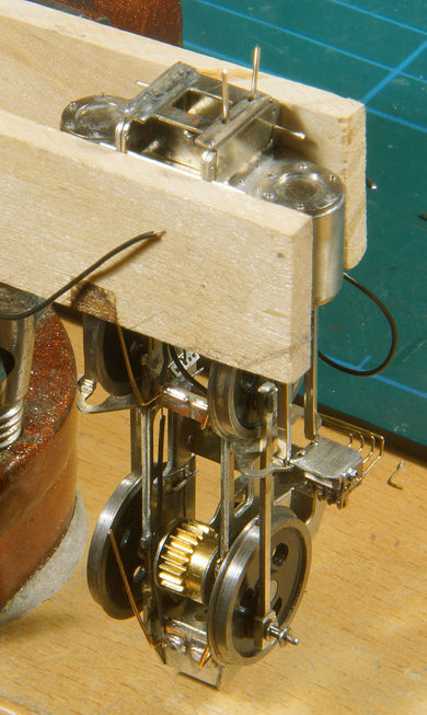
Brake assembly |
|
 |
 |
Before anything else the manual recommends [191] you ream the locating hole in the mid frame spacer to accommodate the 10BA screw's head to fit through. This will be needed to centre the bearing plate later. |
|
 |
 |
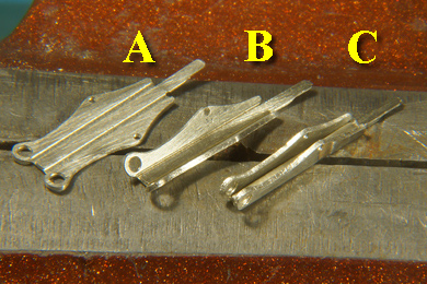
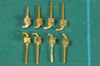
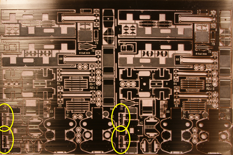
Find the brake hangers (still on the etch, nos 72). Folding is described in [181-186]. A. As straight from the fret (albeit filed and sanded) B. Folded 45 degrees on both sides C. Folded on a suitably wide piece of scrap as shown on the right hand photo The seams are soldered with a snip of 180C solder |
|
 |
The cross shafts come in two sizes. The manual does not mention it. I assumed that the longer version is 16.5mm track and the narrower version for 14 mm. |
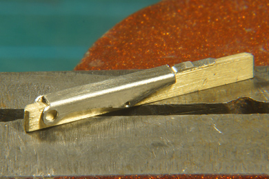
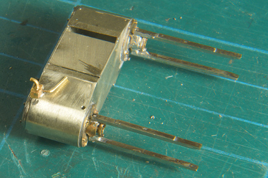
It takes the better part of an afternoon to get all parts of the brake rigging this far. A square on the mat is 10x10mm. Note that there are two types of brake blocks. Both types have come away from the fret when cutting out the frame plates as your very first action in this build, so if you can't find them on the fret they are probably in your storage box. I chose the moon shaped brake blocks, as I followed my 2011 photographic evidence. The brake blocks come in four sets of three. Do not cut the bridges between the three members of each set but use them to fold them together. Solder and file flush. |
|
 |
The manual leaves you in the dark about the order of assembly so I will take the trouble to make this clear.
First run a reamer through the holes in the frame where the 1 mm hanging bar is supposed to go through. You will find at first that this bar will not go through the holes immediately. Ream just until the reamer comes horizontal. Then trial fit the 1 mm bar.
|
 |
File the frame's locating gaps that will take the brackets down flush to the mid frame spacer. |
 |
Insert the 1 mm bar. I determined the suitable size to be 19.5 mm Measure the outer end to be equal on both sides and tack solder one side. Measure again, correct if necessary. Than solder the other side permanently and finally resolder the tacked side permanently.
|
 |
Hang the brake hanger on the bar and let gravity position it. Keep about 0.5 mm on the outside of the bar as the bracket will have be placed over it later. Solder the hanger by sweating it into place. It just needs a little tack. |
 |
As you have reamed the holes in the frame a little and also adjusted the gap in the frame, chances are that the bracket's hole is not quite correctly located anymore. A little filing will help to get it dead flush. |
 |
Solder the bracket over the rod and hanger on the mid frame spacer. Do NOT solder the outer end of the bar yet as the brake will come loose again and move. |
 |
First bring the cross shaft in position by folding the thin ends over the 0.6 mm bars and solder it in place. |
 |
Cut the cross shaft's bars and file the ends flush. |
 |
Then and only then solder the hanger bar's outer end to permanently fix the bracket and the brake hanger. Use a sufficient amount of flux and solder. Do not linger with the soldering iron though to avoid the bracket to come off the mid frame spacer. |
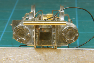
Drain cocks |
|
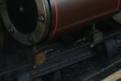 |
Again the manual leaves you in the dark about the drain cocks. Which, when and how. Again my photographic evidence helped out.
|
 |
The castings are not very good so quite a lot of filing went into them. Note the the outside of the drain cock has a small inset detail (all lying outside up). Also note they are handed |
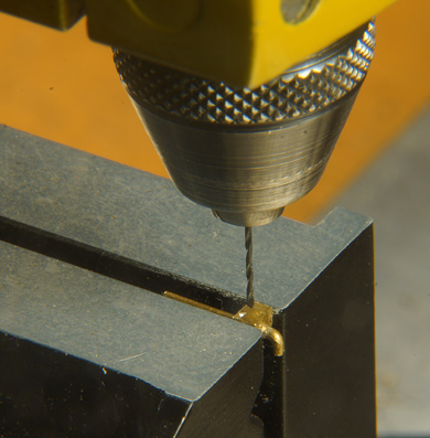 |
To add the steam tube a hole is drilled. Drill in the back of the leading drain cock and in the front of the trailing one. |
Four pairs ready for soldering on the cylinder blocks. Appreciate the steam tubes on the rear and the front of each drain cock pair. |
|
 |
Open up the holes in the bottom of the cylinders to 1 mm. Bend the spigot of the drain cock to approximately the angle of the cylinder surface to get it hanging level from the cylinder. Bend the steam tube to the middle of the cylinder body. Once the the drain cock sits vertical and true, solder it from the rear with 145C solder. Once a pair is installed also solder the steam tubes ends to the cylinder body. |
Done! |
|
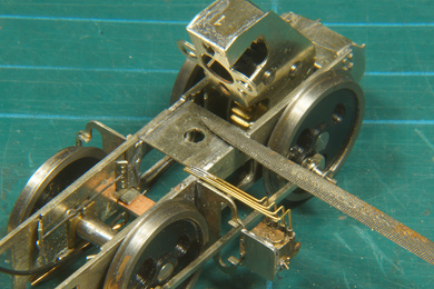
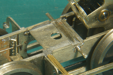
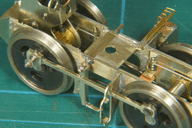
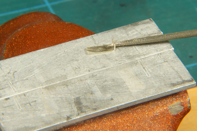
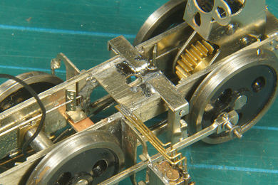
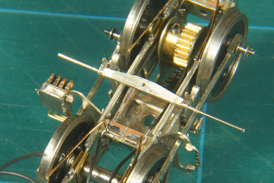
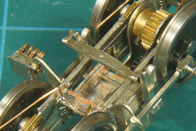
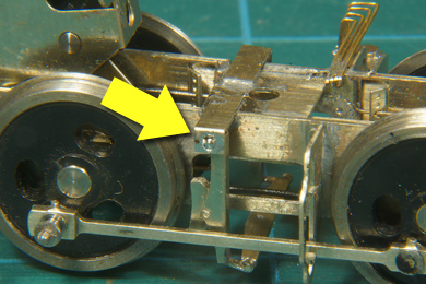
Rubbing plates |
|
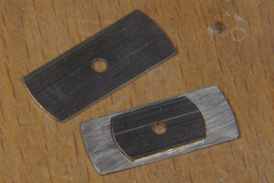 |
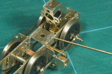
The kit provides scale size rubbing plates but I found them a bit smallish. So I cut two more sizeable ones new from scrap nickel silver. The manual recommends this to reduce wobble. I screwed the 10BA bolt in and simply left it to this as I don't have the faintest idea yet how the locomotive's body and the bogies will be joined. More on that later |

Sign my
GuestBook